Sunday, January 20, 2019

Toaster Trouble


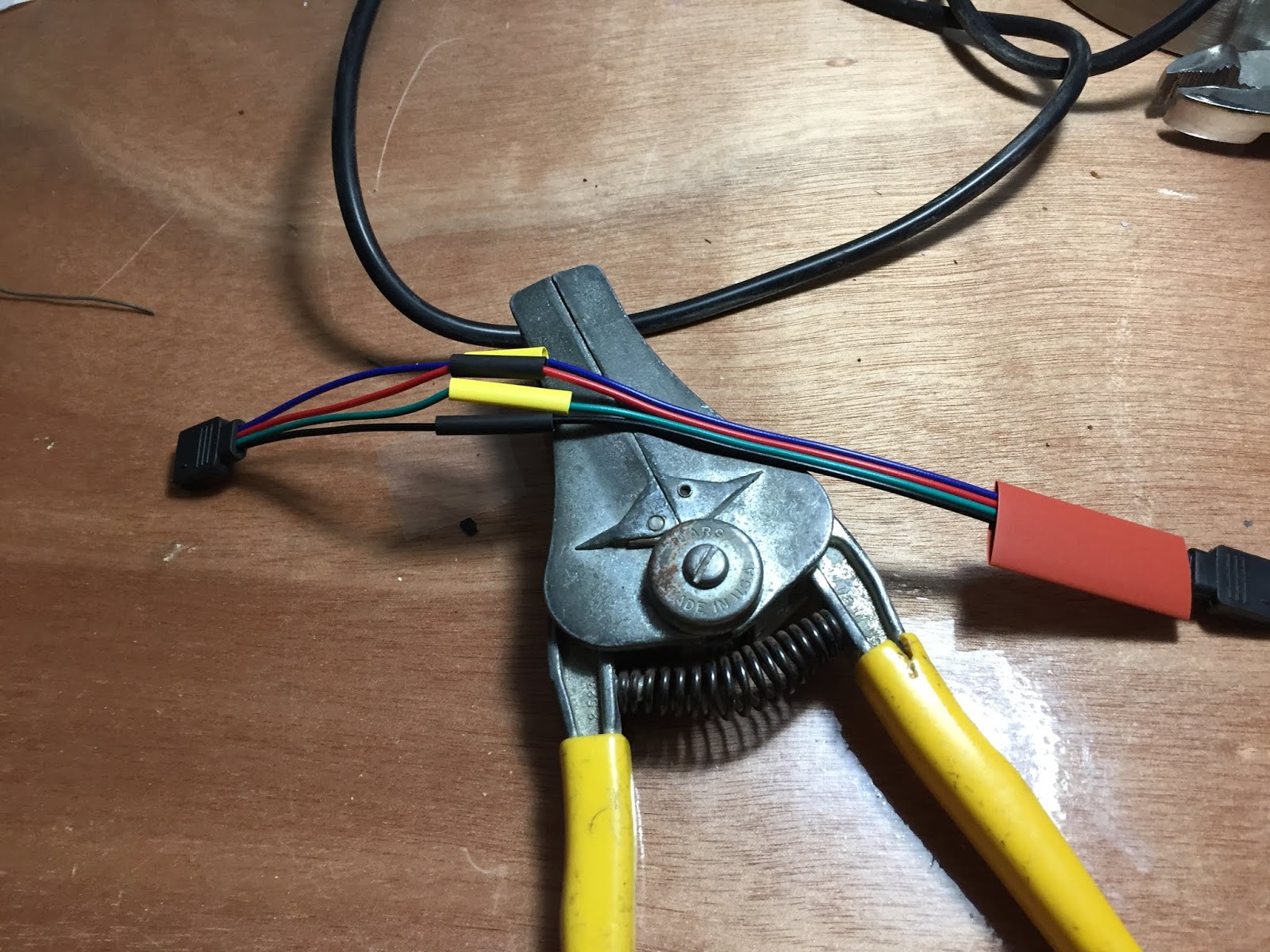
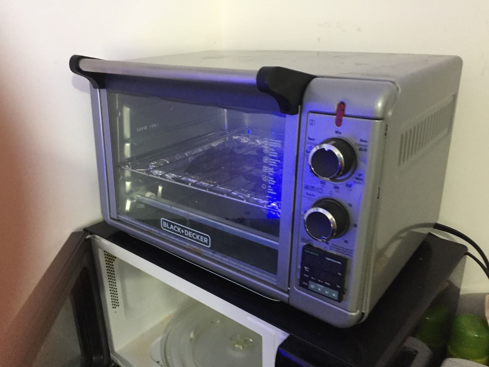
I removed the T-type thermocouple and installed a K-type thermocouple by drilling a hole and bolting the probe so it sticks into the oven area just above the mid rack and towards the back. I also installed the ITC-106VH which I finally received after returning the counter Amazon sent me by accident. I then went through the settings making sure they were right for my application including setting the display to Fahrenheit.

I tried to heat the oven up to 100F but the detected temperature starting going down instead of up. This meant that I had the thermocouple wired backwards so i switched the terminal connections and waited for the unit to return to room temperature. 

When I returned to the project the temperature readout looked like it was low for room temperature so i used my IR-40 Infrared Thermometer to read the temperature inside the oven near the thermocouple and the controller was 6.8 degrees low. I adjusted this in the controller's calibration settings so it now reads accurately at room temperature.

I then set it again to 100F and it had an initial over shoot of 10 deg and then under by 5 deg and tuned in from there. For reference the PID control formula is:  
  • Ts = Sample Rate (How often the formula runs)
  • Kc = Proportional Gain
  • Ki = Kc * (Ts/Ti) Coefficient of Integral Term
  • Kr = Kc * (Td/Ts) Coefficient of Derivative Term
  • en = SPn – PVn = Error Term for Sampling Time “n”
  • M0 = Control Output for Sampling Time “0”
  • Mn = Control Output for Sampling Time “n”


After it sat at 100F (which I did not cross verify with the IR thermometer so it may not have been 100F inside the oven) I set the new target temperature to 350F which it never reached. The controller said it was around 170F but I measured 250F in the oven. Interestingly, I had the same temperature issue with the T thermocouple on the other InkBird controller. 

I think what is happening is that these cheap controllers do not have cold junction compensation build into them. To properly use a thermocouple you need to know the temperature of the wires at the point they connect to the controller. This is known as the cold junction. If the controller is just assuming the this connection is always at room temperature when it is not then the readings are going to be incorrect.

A new Omega PID controller is 100 dollars more then the inkbird but I guess you get what you pay for. So my options now are to try and insulate the controller from the heat of the oven which I dont think will work very well, Try and open and fix the Omega controller I already have, or bite the bullet and spend the money for a new proper industrial controller. 

This would explain the differential in temperature but not why the oven was not able to heat up beyond 250F. Part of that may have been the cover was not installed increasing the heat loss as it was able to reach 350F when it was on before but according to the original knob on the front it should be able to reach 450F.  I may try appling AC directly to the heating elements to see if they get hotter without going through the SSR.
 
The other issue is the circulation fan is still not running.  Is it broken? This was a relatively new toaster oven when I started the project. The oven should work without it though. 


Saturday, January 19, 2019

Finishing up the Hutch Light

When I bought the LED strip for the other project i also bought a splicing kit which actually didn't have anything for this particular situation where I needed a male to male connector to go between the LED strip and the LED controller board. What I ended up doing was cutting two connectors and soldering them together to make a M/M cable. Even though the "White" is still rather blueish I think I am done with this project..  I hope.


Computer Desk Light

I have a computer desk with a hutch and unfortunately not enough light reaches my keyboard and desk surface. So I wanted to add a light. (Cue the comedic music)

Phase 1
I had a spare LED light left over from when I was installing them for room lighting around the house. It is about the same size as a 4 foot fluorescent bulb fixture which turned out to be too big for the lip on the front of the hutch so I drilled some holes inside the hutch cabinets to the wire tie it to the back. This as you may suspect lit up the wall behind my monitors making them harder to see and my keyboard was still somewhat in the shadow of the display.  It was better then nothing but not the right solution.


Phase 2
My next bright idea was to use RGB LED strip lighting because that would just look so cool. So I bought a spool of 5050 RGB LEDs. Actually,  I bought it for another project but that one only needed a couple feet off the spool but I used the controller it came with for that project. Because I didn't have
a controller I connected it to my variable power supply and figured out that the +V goes to the black wire and the Red, Greeen, and Blue wires connect to ground to turn the LEDs on. I then found a 12V 2A power supply I wasn't using anymore and wired it to the strip tying the three colors together to GND. This means that all three LEDs should have the same current running through them. This does not actually produce white because each LED color has a different forward voltage so the light was more of a blue-white.

However, after about 24-hours of being left on it started to flash. I checked the supply and it was overheating which was causing it to perform short thermal shutdown cycles. I then dug up an old 12V 5A supply and wired that to the strip which did the trick.

Phase 3
For ultimate coolness I needed an LED strip controller. So I ordered one online along with some screw terminal power connectors to make rewiring easier.
I only needed to use the male part of the rewiring connector because the controller already had the female part. Unfortunately, both the part that connects to the LED strip and the controller connector are both female. So I am going to need to find a 4pin male to male connector or just some stiff wires of thr right gauge.

Thursday, January 17, 2019

Improved Toaster Oven

This project started because I had an Omega PID temperature controller that was laying around forever and I thought it would be nice to have an accurately controlled toaster oven. I mean an industrial PID controller must be able to regulate the temperature withing a few degrees which has to be better then the bi-metal system that these things use, right.

So I took it apart and cut the connections to the existing controls and used a tin snip to cut out a square hole for the 1/16th DIN controller. I added a sold state relay mounted on a heat sink the was to be controlled by the output of the controller. I used a T type thermocouple which I fed into the recirculating fan chamber. This is where I found out why the controller was just kicking around. It was broken! Specifically, it would not turn on the voltage output to control the SSR. (Solid State Relay).

I then, (actually many months later), bought an InkBird PID ITC-100VH controller. After installing this I noticed that I had a new issue where when it turned on the SSR the voltage would drop to the controller causing it to reset and turn off the controller. Once it finished coming up it would turn on the SSR, rinse and repeat.

After much thinking and poking I realised that the point I was taking one of the AC legs to power the controller was after it had already gone through the light. The light acts like a resistor which is what caused the voltage drop to the controller when the SSR turned on. The light only actually illuminates when there is a lot of current going through it. So it only lights when the heating elements are on. Moving the power line for the controller to before the light fixed the drop out issue.

I then wanted to change the controller from C to F, because AMERICA, when I realized that this controller only operates in C. Really why would anyone make a smart controller that wont do basic conversion math! Well I don't want to have to do the conversions myself everytime I want to cook something so I ordered an InkBird PID ITC-106VH which is the exact same controller at the same price but this one does do both C and F operation.

When it arrived I removed the ITC-100VH and in opening the new one I realized they sent me an Industrial counter instead. I started the return/replacement process through Amazon and because I was frustrated and wanted pizza I put the ITC-100VH back into the oven and set it to 190.5C which is 375F.  However, I never saw the heating elements glow red and after an hour it still did not reach its target temperature on the controller. Using a IR temperature measuring device I opened the door and took a reading of 357F.  It would appear that the oven balanced out at around this temperature. (heaters vs temp loss) I don't think it was reading the temperature accurately enough either possibly because the thermocouple was in the recirculation section which may not have been running.  When the correct controller arrives I will also check if the fan is running and possibly change the thermocouple from a simple T type twisted wire to a K type probe mounted in the oven chamber directly.


Wednesday, November 14, 2018

MAME Arcade Project

Sometimes I will get an idea in my head and it will become an all consuming obsession until I at least make an attempt to make it a reality. This is the case with the MAME Arcade Project. I was on YouTube and saw an episode of "All Work and No Play" where they had a MAME arcade constructed and from that point on I had to build one. Even knowing it's pointlessness and expense it was something that I had to do or at least attempt. 

MAME stands for Multi Arcade Machine Emulator and this is software that will run the original ROMs from the Arcade machines of my youth. But it is not enough to just run this software on a PC. In order to get the full original Arcade feel you need to build it into a full Arcade cabinet. Imagine an entire arcade in a single unit!

I started obsessing over full size cabinet designs and how I might be able to build one when I saw the Arcade1UP Galaga machine in Walmart this year and thought "What a great short cut!". It even had the display mounted on its side to get the same arcade screen ratios of the early games.

So in order to do this project you need to determine the model number of the LCD display inside the machine because you are going to need to buy a video interface board from amazon in order for it to display HDMI video. In my case that was an M170ETN01.1 [Amazon Link to Video board] To install this you need to remove the box attached to the back of the monitor. This is the actual Arcade1Up game control board and you want to unplug the video cable from it and attach it to the video board that you bought and affix it to the wood frame of the display. The video board comes with a button board you should also affix to the frame in case you need to change some video settings like contrast etc. The other board is a voltage converter for the LCD back-light which I did not need to use as the monitor had it built in. There should be a cable coming out of the monitor that will plug into the connector that would go to the board that you don't need.

I used a Raspberry Pi 3b+ as the new brain of the machine connecting the HDMI video to the display board. I then also connected the Audio out from the video board to an amplifier that I mounted to the back of the unit. [Amazon Link to Amplifier] Cutting a hole in the back cover for it so I can reach around and set the volume bass and treble. I then mounted speakers to the panel that goes on the top of the cabinet. [Amazon Link to Speakers]

I should specify that I thought out and mounted the amplifier and speakers BEFORE assembling the cabinet. You could do it after building the cabinet but it might make things harder. Also a note about the Raspberry Pi. You are going to want to use the Retro-pie image for your machine; however, this does not come with any actual game ROMs installed so you will need to find these on your own on the internet or find an already populated Retro-pie Image.

To be continued...